What are the requirements for common mode inductors?
 31/01/2019
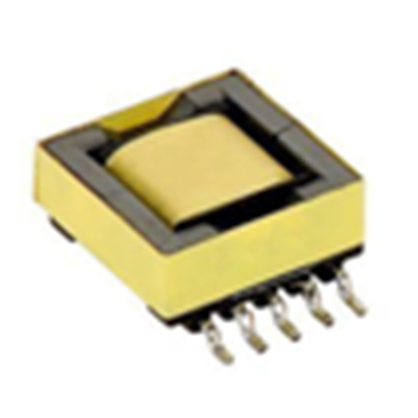
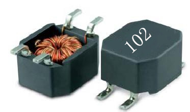
Common mode inductors, also known as common mode chokes, are commonly used in computer switching power supplies to filter common mode electromagnetic interference signals. In the design of the board, the common mode inductor also acts as an EMI filter to suppress the electromagnetic radiation generated by the high-speed signal line from radiating outward.

Overview
The design of the line filter is usually considered from both the common mode inductance and the differential mode. The most important part of the common mode filter is the common mode choke. Compared with the differential mode choke, a significant advantage of the common mode choke is that its inductance is extremely high and the volume is small. An important issue to consider when flowing a loop is its leakage inductance, which is the differential mode inductance. Usually, the way to calculate the leakage inductance is to assume that it is 1percent of the common mode inductance. In fact, the leakage inductance is between 0.5percent and 4percent of the common mode inductance. The impact of this error may not be negligible when designing chokes with optimal performance.
Common mode inductance requirements
(1) The wires wound on the coil core should be insulated from each other to ensure that no breakdown short circuit occurs between the turns of the coil under the action of instantaneous overvoltage;
(2) When the coil flows through a large instantaneous current, the core does not appear saturated;
(3) The magnetic core in the coil should be insulated from the coil to prevent breakdown between the two under transient overvoltage;
(4) The coil should be wound as much as possible, which can reduce the parasitic capacitance of the coil and enhance the coil's ability to withstand transient overvoltage.
Under normal circumstances, at the same time pay attention to select the frequency band required for filtering, the larger the common mode inductance impedance, the better. Therefore, when selecting the common mode inductor inductance, it is necessary to look at the device data, mainly according to the impedance frequency curve. In addition, pay attention to the influence of differential mode impedance on the signal, mainly pay attention to differential mode impedance, pay special attention to high-speed port.
 133-9291-8466


 133-9291-8466
 semcms
 13392918466